The sub RX has quite a high noise level with the antenna disconnected. In actual operation, when scanning dead bands or with weak signal conditions, the hiss-type noise is irritating. With the preamp 1 engaged, the background hiss is far less noticeable. But after performing the Sub RX 3 KHz roofing filter mod which transplants the roofing filter from a FT-9000 into the FT-2000, I wanted to look into the noise and complete the tweaks to this part of the rig. Basic Analysis and OptionsThere are generally four possible sources of the noise: - IF amps
- AF amp
- Mixer byproducts
- LO noise
I don't have proper facilities to directly measure for noise. However, the answer can be teased out with a bit of indirect analysis. First, I did some testing of the IF amps – adjusting the gain manually via the AGC line and looking at the SNR of a weak signal on the AF scope. The AF amp can be considered clean – because when the IF gain is turned down, the AF output is pretty quiet. I think this suggests the AF chain is not the primary cause. And the constant SNR with varying levels of IF chain gain suggests the IF amps are not the source. That leaves the mixers and the LO as the potential noise sources. Here the sources can be narrowed considerably. Pulling the 2nd IF mixer LO results in a moderate change in the noise level and so I think the issue is specific to the 3rd mixer or the 3rd mixer LO feed. I don’t have a way directly to test the LO but the spectrum looks pretty clean (the scale is correct for the SNR but the absolute level is not calibrated) – with the noise about 90-100db below the carrier. The floor here is likely the limit of the sound card and not necessarily that of the LO source.I can do one other test – replace the 2nd LO and 3rd LO with the Si570 sig gen to see if that improves things. But beyond this, I am out of ideas at this point. After quite a lot of toying about on the bench, I decided that the most effective way of addressing the rig noise was to modify the AF passband to roll off the top end. This does not fix the specific source of the noise, but my hope was that the added filtering would take the "edge" off of the recieiver response and as a result providing a much more listenable receiver. Simulation of the Rig's AF Section The first step was to simulate the key buffer amp parts of the sub AF chain. And then take a look at what value adjustments could be implemented to provide a high-end roll off. The stock configuration of the rig has an approximate 2.4 KHz -3db point. Taking a look at the AF stage of the sub RX, there are two key blocks which invite modification. The summing amp Q4537 and the buffer amp Q4536. Power amplification driving the speaker and headphones is done on the main board. Note that modifications to this circuit here will affect the AF OUT jack on the back. So consideration should be given if you drive a waterfall type program with the sub RX. 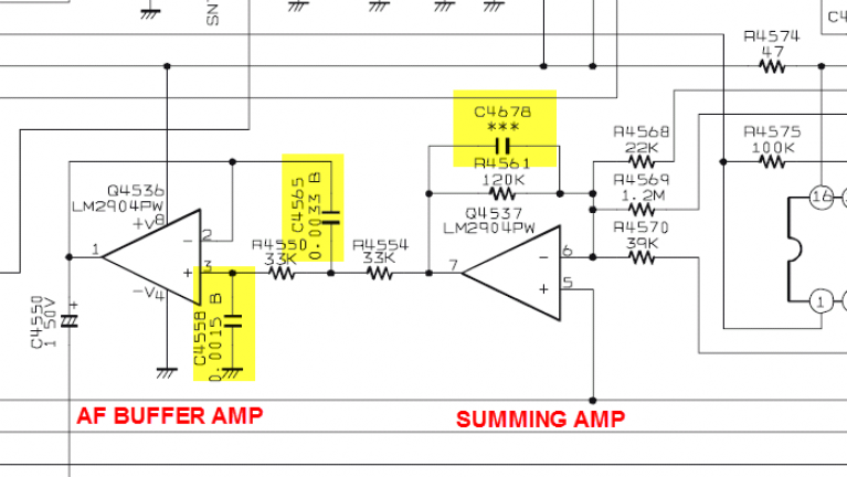
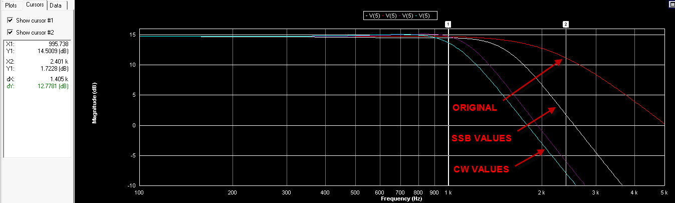
Simulations were done in eSketch which is a very fast utility for these kinds of filter programs. And while the filter curves could be built with a filter design program, small adjustments to the caps on this circuit are the easiest way to see the effect. The results of the simulation can be seen in the plot below. The RED trace is the plot that the stock rig exhibits. SSB values in WHITE, and a pair of CW curves in purple and light blue. 
New component values for each of the curves are show here: Component | Original Values | CW 1 KHz | CW 900 Hz | SSB 1.6 KHz | C4558 | 1500 pF | 1800 pF | 1800 pF | 1200 pF | C4565 | 3300 pF | 0.0012 uF | 0.0012 uF | 8200 pF | C4678 | {none} | 1500 pF | 1500 pF | 1200 pF |
For my objectives, I decided on a 1 KHz corner frequency target because I often do RTTY work in the 900-1100 hz range. In addition, the narrow response of the 2nd IF CW filter rolls off around 800 Hz. Setting the AF roll off above this point would ensure the filter passband remained flat. This setting provides the maximum attenuation of the hiss in all modes, while being optimized for nearly zero roll off of the CW/RTTY 1K and below segment. At frequencies above this, around 12db of attenuation is provided by the roll off at 2Khz and above. Sub RX AF Mod Steps The mod is simple to do. The top half of the clam shell case provides access to the sub RX. And the work can be done directly on this board. The best way is to parallel the needed value with the stock caps. In this way, no components need to be removed. The cap sizes are in the SMT 0603 category - for my modification, I used 0805 because they are much easier to work with. And because they set on top of the 0603 components, they don't need to be exactly the same size. NOTE: The component values in the table above are the FINAL values needed - not the added values required. In the case of a SSB mod, the C4558 cap needs to be removed and the lower value cap put in it's place. The mounting points on the circuit boards are also very convenient - in focus here by the green highlights. 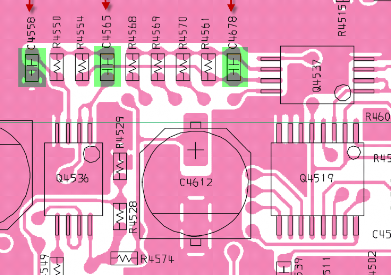
First, the solder points of each of the 3 caps were solder-tinned to make mounting the additional caps easy. Next, position the caps over the top of the basing cap and solder each end to complete the modification. Sub RX AF Mod Measurements Top light blue line is the original AF plot - with the 2nd IF filtering bypassed – the steep drop off on near 4 KHz is due to the new roofing filter. With the cap value changes, the new signal response becomes the Orange/brown color (top red arrow). I'm primarily a CW op and so the roll-off starting at around 1KHz fits my operating style. A slight change in the cap value would cause the roll off to occur at higher frequencies and would be more suitable for SSB ops. The same attenuation trend is of course at work on the no-signal noise floor - which the bottom curves represent. Here the original response characteristic is shown in green. The pink and purple lines show the individual cap changes - with the dark blue line (bottom red arrow) representing the final step with all the part value changes implemented. 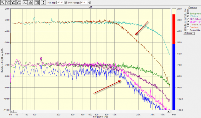
NOTE: This rig has the 1K mod which provides a 2.2 KHz filtering width in both the CW and SSB positions. For more details on this mod, follow that link and scroll down to the lower part of the page. With the 2nd IF filtering enabled, the combined filter responses can be see here. The light blue line is the SSB mode wide setting with the IF shifted -300 hz via menu. Recall with the 1K mod, the fixed passband's of 2.2 KHz is adjustable for center frequency by menu setting. The light pink line is the CW mode wide - with a -300 hz shift mode. The brown line is the CW narrow using the Inrad 300 hz add-in filter. The filter vertical slope effect is easy to see - and at the point where the noise floor is encountered, the roll off of the Sub RX AF mod can be seen in effect. 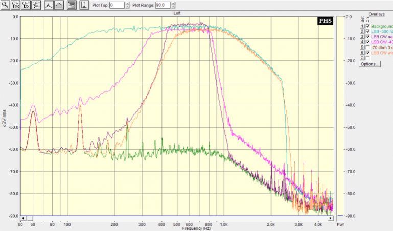
Note: The bumps in the noise spectrum at 60/120/180 hz are artifacts of the test setup and are not present in the actual rig. Sub RX AF Mod ObservationsI love this mod! The hiss level is far less with the cap changes. And while the top end of SSB conversation is significant, it's still functional for that mode. Most importantly to me as a CW and RTTY op, the listen-ability of the sub RX is hugely improved in the weak signal condition. While the root-cause of the hiss remains unaddressed, the Sub RX AF mod changes are easy to make, reversible and customizable. Which makes this a very nice project for someone interested in taming the hash present on weak signal work with the sub RX. |