 Dynamic range is something of a challenge for rig makers now. Even with great AF dynamic range, the capability of DSP can push the noise floor down to the point where it's hard to hear the band noise. And the band noise level is where the DX is. Solution? Turn up the volume. Dynamic range is something of a challenge for rig makers now. Even with great AF dynamic range, the capability of DSP can push the noise floor down to the point where it's hard to hear the band noise. And the band noise level is where the DX is. Solution? Turn up the volume.
Problem? Sometimes it's still hard to hear the rig. Tiny speakers. Tiny amplifiers. And a progressively harder time hearing as one ages. :) What follows is my solution to the volume problem. Sure 2x50W Class-D Tripath-based AmpInside the speaker enclosure is mounted a class-D AF amp that is really fantastic. The SNR is good and it’s flat-flat in response. The amp has a lot of power and due to it's switching orientation, has pretty low heat dissipation making the usual power supply concerns less of a problem. Why 50W? A smaller 2x15W amp is available at about 1/2 the cost - but to my thinking, clipping is what kills speaker coils and is the leading cause of lousy sound. And considering the amount of work required to build the amp into it's enclosure, it seemed a better choice just to put the larger amp into the box and know the headroom is there. Just in case... The module looks like this. It's about 4x4" square. Power supply levels range from 10-32V with varying increasing levels of power output as the input voltage ramps. I’m running this amp off of a 19.5V 4.75A switcher. Buffering the board from the switcher is a LPF pi-net with 0.1 uF on each side and 2.2mH power inductor. On the board side, there is a 47K uF cap just for added measure. I purchased the board from a US suppler and the delivered cost was $48. Rated at 50W RMS x 2 channels with 0.01% THD and a 80db SNR. The amp has two of the TK2050 chips which are capable of 2x25 or 1x50W operation with considerable headroom. In this configuration, each TK2050 chip is setup in a mono configuration which is one of the reasons the THD is so good at the 50W output level. Chanel isolation is also very good. Out of the box, it’s by far the cleanest part of my speaker project. In looking at the schematic, I noticed that the input circuit has an op-amp style driver type and it got me to thinking, would it be possible to do a bit of work and add some HP/LP features making it an even better fit in it's role as a communications amp. 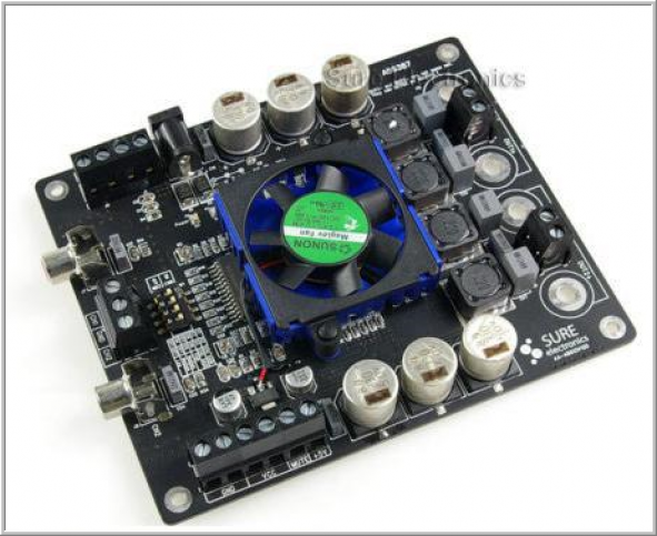 Only two funky things with this board. First, the fan is connected to an on-board regulator and there is some feed-through noise. Fortunately, the amp is so efficient the amount of heat generated in communications service is negligible. So I just pulled the fan off and left the heat sink remaining in place. The amp idles at about 35C. I don't know what the powered level heat is in use but the sizeable heat sink. The other minor issue is that the output nets both float – so none of the 4 speaker wire connections can be shared. In this application, that’s not a problem other than to ensure the external speaker jack is not grounded to the board. Mod Design IdeasWith the input terminated into a known Z, and the output given by the data sheet, some good guesses could be made on the effect of surgery. I focused on the input values for these items. Lower cap values will tend to offer a low end roll off. And R16/R30 is part of an input network feedback. Putting a cap across these resistors should give some high end roll off. 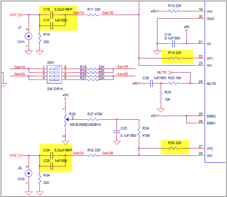 All components are accessible from the top side of the PCB and I did not remove the board from the speaker mount to make the mods. C16/C25 were cut away and replacement values were fitted in the location of C16/C24. 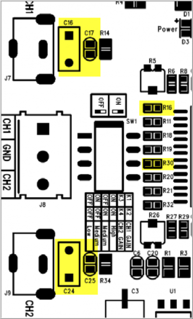 SimulationFirst step was to take a look at the schematic play a bit with the values to see if the idea was workable. R4 is not shown on the schematic and is based on datasheet comment of 2K input Z. But it’s not much of a factor in the sim results even if it turns out to be quite a bit different. 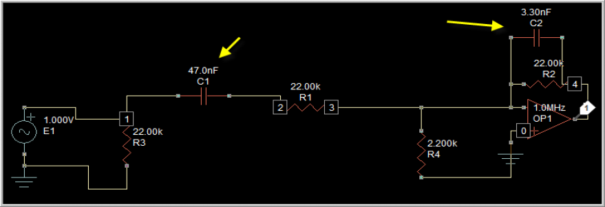
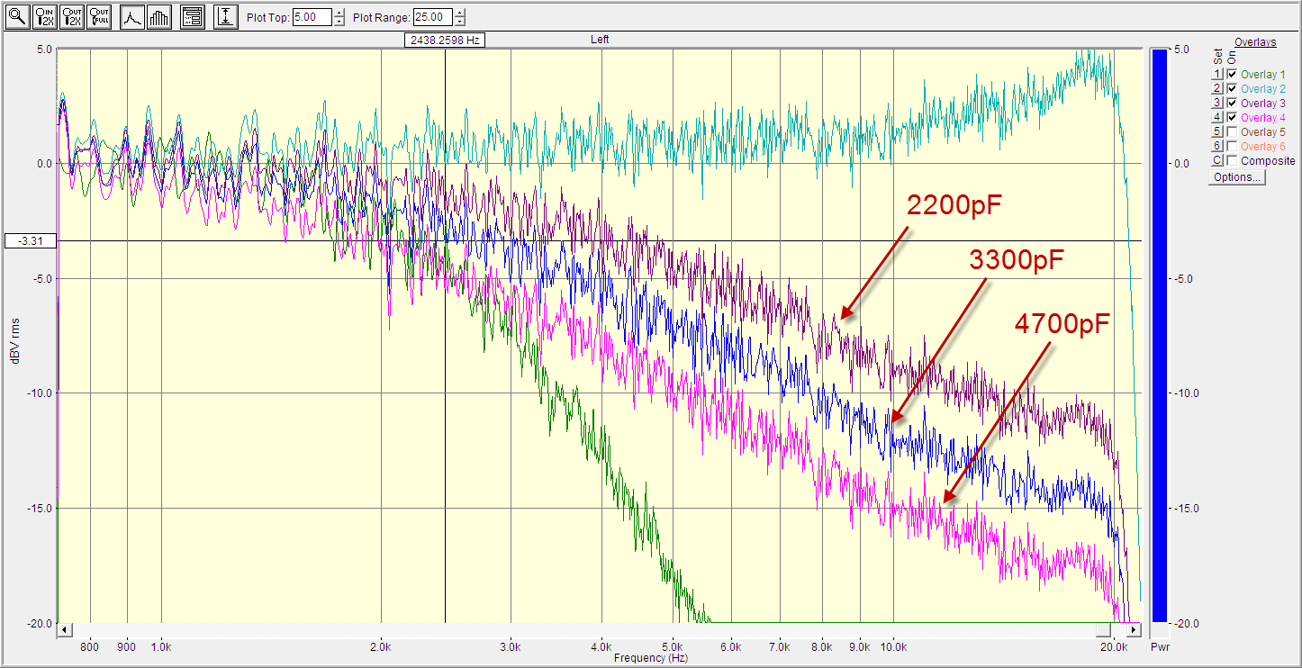
On the top end, I picked 1800 pf which makes the -3db point 4.2KHz - because I will match this amp with a filter board which has considerable roll off. When used alone, 3300pF makes the -3db point about 2300 hz, based on the simulation and is a very nice mixed mode value choice. 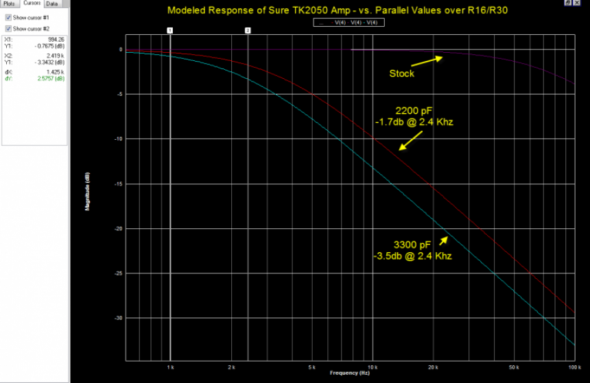 This amp module has an on-board dip switch which allows for other input gain settings - R1 in the sim schematic above can change between 22K, 11K, and 7.3K corresponding to a 24/30/34db of overall gain. Normally I would run the amp at 24db but if a higher output level is needed, what’s the effect? The purple trace (below) is the 24db setting and that’s what the design work was centered around. Changes in gain serve as part of the input LPF circuit and we need to consider changes in the gain with respect to the frequency response. The light blue trace shows the 34db gain position. At this gain setting, the -3db points there are 350 hz and 3 KHz. -6db at 220 hz on the low end. For a CW op, these are fine settings - SSB ops who like a more lively bottom end would want to pick a bit lower feedback cap value. The low end could be extended with a bit higher input cap value - a 0.15uF value gives the same 130/2.5KHz at this amplification level vs. the lower gain setting. The top end is more or less unchanged with gain adjustment. 0.082uF seems a good compromise value if various gain settings may be used and the risk of 60 hz hum is not a worry. The speaker filter board has an overall 12db gain at max volume settings so the variable gain, in this application, may not be needed. 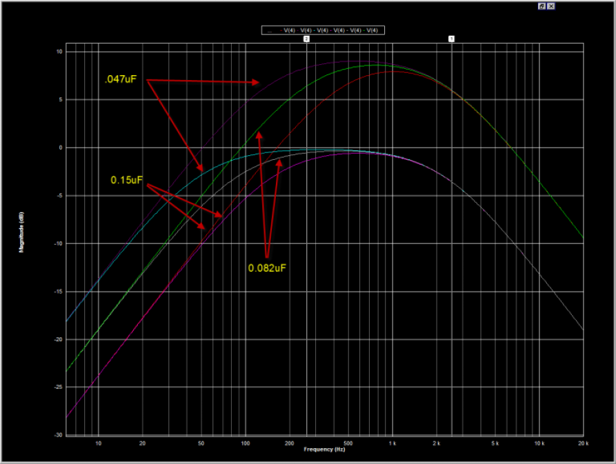 Performance MeasurementsSo much for simulations, what’s the actual result like? Blue line is the output before mods. Red/Orange/Blue-ish line is the output after mods. 20-20KHz view here. Match to the simulation is pretty close when adjusted for the effect of the transformer used to sample the speaker output - the low end roll-off is less in reality as this is caused by the transformer used to couple the floating speaker outputs to the sound card input. Not sure about the float upward on the high end – it’s not there in the direct coupled case so I think it may be related to the transformer as well - or the amp may have a slight upward gain bias. Data was taken with the Yaesu internal speaker connected in parallel with the 600:600 transformer. Around 10db of 60 hz attenuation I would guess based on the curves seen here. 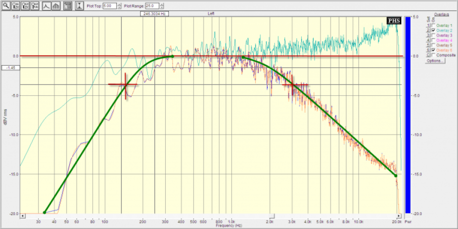 While trying a couple of different feedback cap values, these plots were taken and match up quite well with the simulations. Again, the higher values are of more interest to the CW op. At 1800 pf, the -3db point is about 4.2KHz. 
And here, a close up view of the actual communications spectrum. 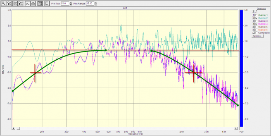
The board shown here mounted in the SP-2000 case near the rear. The fan is still fitted in this view. The risers are mounting pegs for another project - an microprocessor driven AF filter board. Click HERE for details on the filter board. 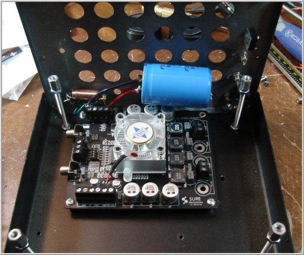
I love it when a plan comes together. And here at AC0C, that’s not very often indeed. 73/jeff/ac0c |