3 bands, 3 elements - and a 80m dipole for good measure This project started out as a simple search for a 20m replacement. My friend K0RU is a wire-beam crazy nut and convinced me that a 20m wire v-shaped yagi would likely fit. And with that basic design, I started to work with MMANA-GAL. The 20m beam looked great and then I got to thinking about putting traps on the beam to get it to work dual-band on 20/30m. And later, 40m. The final design, in MMANA-GAL, looked like this. 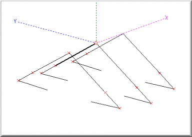
The project's history and results follow, explained in a letter to my Elmers, 1 Aug 2008 ===================================================================== Gentlemen, Sorry I’ve not been attending to your emails and replying properly – I’ve been living in the attic for the last 5 days taking the wire beam from concept to reality. FIRST - thanks to everyone for their comments and feedback, especially Rob and Bill – for having the patience to listen to my endless babbling about the antenna and for providing some great ideas and a sympathetic ear at critical times. And of course, to Patrick Wong, VE3RGW for his original “3-element Ninja wire beam” article, which this concept is derived from. Check out his original work on p163 of the ARRL Antenna Compendium, vol 7. I want to praise the writers of MMANA-GAL; that is one fine bit of code and I could not have done this project without it. I suppose I have around 80 hours of MMANA-GAL time in on it over the past few months, and if I were using another solution that did not allow for the weighted-optimization adjustments, I think it could have taken months to come up with a design as good. It’s up now, working nicely - and there are quite a few bits of good news… - After building up the traps, the dimensions were optimized for the individual trap actual center frequencies – and I found a reference pointing to the typical Q of the coil vs. frequency. That allowed me to tighten up the design quite nicely.
- Next, as luck would have it, the traps serve to shorten the element lengths. It was just enough for me to maintain a full and uniform inverted-v shape. That really cleaned up the compromises we had seen in the preliminary design on 40M.
- As far as the actual performance, Rob helped me run some informal f/b testing using the s-meter on the FT2K, and the MFJ-259 as a point source. I went to various points on the compass away from the house about 200’, and Rob recorded the f/b numbers. Here’s what they came out looking like, in summary:
- 20m – 3-4 s-units difference f/b along the axis of the beam, and 5-7 at 45’degrees off the back side.
- 30m – 1-2 s-units difference f/b along the axis, and 3-4 at 45’ degrees
- 40m – 0-1 s-units difference f/b, and about 2-3 at the 45’ nulls.
- The only implementation issues encountered, other than the need to climb up in the rafters after each trim, were two:
- On one of the directors, the R at X=0 was about 55 ohms. Just as in the model. But the other end, identical in configuration, showed about a R=15 at X=0 on 20m. it took me quite a while to figure out what was causing the problem. It turns out that the detuning was caused by capacitive coupling to the wire mesh that underlies the stucco exterior finish on that end.
Moving the element away from the wall about 2m showed an improvement in the feed point resistance, but I KNOW that the antenna pattern would be seriously compromised by moving the element so close to the director. So in a final design compromise, I moved it the 16”-rafter-spacing away from the stucco exterior wall. And adjusted the model to see the effect. It was minimal, and so there it sets. I was very happy to see that, based on the F/B testing, there seems to be little practical impact of having the mesh there, other than to show up in the feed point resistance.
- Trimming a trapped antenna is not at all like trimming a regular dipole. The relationship between frequency and length is strongly influenced by the traps. For example, to move the resonance down about 100kc on 20m, I needed to put about 9” of length into each side. The traps are very dominant. On a standard dipole, about 1 inch would have done it. The 468/f has little meaning. We were able to verify that in the model this is indeed the case, but it was my first go-around with traps so a bit of a surprise for me… I will have to look at the model to see if the same behavior is shown in MMANA-GAL.
Although the antenna loads fine with a comfortable SWR on the CW/data ends of 20/30/40, I did keep the attic-mounted MFJ-996 auto-tuner in the line. That gives me more flexibility in case I want to play on the SSB segment, or go to some other band. It’s attic mounted and remotely controlled. I have found the hard way that the tuning of the elements is **THE** key factor in the antenna’s performance. You can see a mis-tuning of 50kc on the s-meter. In the end I managed to get the individual element's trim within about 10 kc of the target. So my advice for anyone else considering one of these wire-beam ideas is to believe in MMANA-GAL’s resonant frequency solution, and ignore environmental factors (because it’s too hard to reasonably model them) – just focus on tuning the antenna to the model’s x=0 frequency. The final design looked like this, from a perspective view. The longest elements, in the center, are a total of 9.3m (about 25’) long, spacing is about 3.2m between each element (about a 19’ boom length). Also shown in this drawing are the 80m traps/extensions - see details on this at the end of the page. 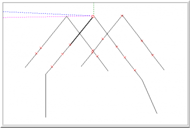
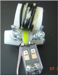
There’s not much of a picture to take of the antenna itself. It looks just like a set of 3 home-brew trap inverted v’s. The interesting idea that I saw in Patrick Wong’s article was to use the center inductor to convert a director into a reflector electrically by switching in an inductor. Here’s what that construction detail looks like.
The model called out a 1.17 uH value and that was created with 5 wraps of the #14 flex-weave on a ¾ inch PVC form. Trimming was done using the MFJ and an LC meter (thanks Charlie!!!). Then tacked down with an expanding glue. Using the insulator and the screws allows for easy attachment of the wires to the relay/coil assembly – a real benefit when doing the trimming. For best accuracy, I put the MFJ right at the feed-point to do the trimming. 40m plot – in our testing it was hard to tell if this F/B is matching reality or not. There is a difference, but need to use the antenna more on some nights that 40 is open and can get a better feel. 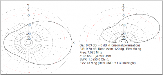
30m plot – The f/b on this graph is not at all confirmed in our tests. It measures more like 6db. The side-lobes are proven to be this deep in the “range testing”, however. 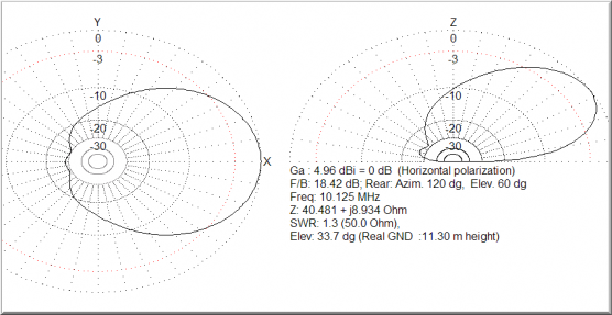 20m plot. As far as I can tell, this pattern is pretty close. I think the rear lobe is larger, but the side lobe rejection seems to match-up in the field test. 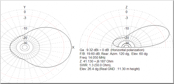
15m plot. The antenna actually has about a 2.25:1 SWR on this band, far from the model prediction. I think that means the pattern will not look anything like this as well. But it does provide a path to get on that band. 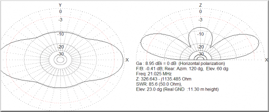 17m – this one is for Adam. With the tuner, I can load up on this band. And I hope you will entertain a QSO sometime, just to prove the blasted thing does work there. Hope the side lobes on this frequency are not this tight either or we may be in trouble…. 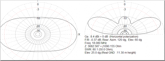
And finally 10m. Just for grins. 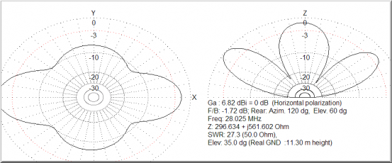 The tuner’s range is not enough for it to load up on 80m, sorry Larry… Rob has already put a bug in my ear about switching in loading coils to make it resonant there, but I’m NOT LISTENING NOT LISTENING NOT LISTENING… Looking forward to the PSK rumble this weekend. And wow, if we had a few sunspots, that would just be the best of all things! 73/jeff/ac0c 1 August 2008 ===================================================================== 80m Extension About 3 months later, I added traps to the driven element to allow 80m operation. The traps provide an inductive loading as well shortening the overall length needed for the antenna to become resonant. Stubs were hung on each end of the individual traps and trimmed for the length. The resonant frequency was set at 3580. The tuner would allow for operation away from this point to cover most of the 80m band. With that extension, the antenna provided 80-10m service with 3 bands having reversible 3-element beam performance. Shortcomings The antenna worked well given the knowledge that I had at the time. Over the year of operation, several shortcomings were discovered - ultimately it was these shortcomings that lead to the Generation 4 Antenna Array. Coax Traps are not stable in RTTY power operation - Initially the design was built with RG-59u. Later traps were built with RG-11. The failure mode in both cases, I believe, was due to the use of too small of a diameter core. The traps heat under severe service duty and that allows the center conductor to move. Eventually the center conductor comes close enough to contact the shield and short the trap. Toward the very end, I had used 6" forms with the RG-11 and despite it's foam center , those traps proved able to withstand the heating.
Single band optimization - The tuning of the antenna with the use of traps has a tiny window of operation where the F/B is optimized. Generally speaking, the resonant points of the antenna between director and reflector duty are -5% and +5% in resonant frequency. The reversing is accomplished by switching the inductor in - the added inductive reactance causes the shift. However, the shift in frequency that results with a fixed inductor value drops with lower frequency. Which means, the antenna is really optimized for just one band. And you basically take what you can get on the others. Sticky traps - The traps tend to dominate the frequency of the antenna near their resonant frequency. Which makes "trimming" the element more difficult. Large changes in length, compared to what would be expected in a full sized dipole, are required. This somewhat further minimizes the effect of the switched inductor. And for this reason, the best performance will be on the band where the antenna is full-size. In this case, the optimal performance was on 20m. Mistake in construction - I found out when rebuilding the beam to the Generation 4 Array, that one end of the element was hard-wired as a reflector. I discovered this using the VNA - as the resonant frequency did not change. It was hard to determine this using the MFJ-259 as this element was the one proximate to the stucco and it's wire mesh underlayment which minimized the "dip" that we see in an antenna further away from this wall. |