In my antenna configuration, there is a high coupling level between 15m and 20m. So I was very interested in seeing what a simple shunt trap could do. The build of the 15m BPF module provided just that opportunity. Why Add Traps to the 5B4AGN BPF Box?Traps in the box are logical as part of a comprehensive signal and harmonic control program... 1. For the receive function, a trap provides attenuation of a strong signal to prevent rig overload (desense, IMD products, noise floor increase). It can serve to augment band combinations where the BPF module alone is inadequate.
For example, the 15m BPF provides about 35 db attenuation to a 20m signal. Adding a single L/C series shunt trap tuned for 20m into the 15m filter module can push the net 20m attenuation beyond 50 db. 2. For the transmit function, a trap provides attenuation of harmonics and transmitted wide-band noise at the source. This is important because an in-band signal cannot be filtered on the receive side. The transmitted signal must have the harmonic (or in-receiver-passband) attenuated. common example of this would be the 3rd harmonic of the 40m signal. It cannot be filtered by the receiver - because the RF energy is already at 21 MHz and thus passes through the 21 MHz receiver's BPF and preselector set.
3. The automatic band switching capability of the filter box makes adding L/C traps into the box ideal because the usual switching problems are already taken care of.
4. The alternative to fitting traps would be to change the Chebyshev style filter design to a Cauer style. However, this would require changing of the main filter elements including the very expensive custom TAB manufactured caps. The use of the traps is quick and easy, and in the event it's not needed, or frequency adjustment is desired, the traps make that an easy action to take. For these reasons, and given what I anticipated was strong coupling between my 20m and 15m beams, adding traps into the 5B4AGN box seemed an easy way to get more attenuation - targeted right at the possible trouble spots. Proof of Concept The test traps were built from T106-6 cores with 16 and 18 GA wire. 18+18 mica 500v caps were used in parallel. The trap was trimmed with the VNA prior to building the rest of the BPF. 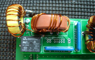
The result is roughly a 15 db further attenuation at the trap frequency. Impact to the passband of the BPF is negligible. But there is a small SWR disturbance. To accommodate the SWR, build the trap first, and then the BPF. So that the BFP trimming takes counters the SWR effect. 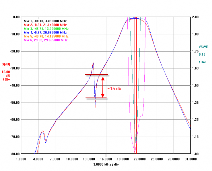
The actual attenuation depth depends on the L/C ratio, Q and operation range. For the final version, some more experimentation will be needed to determine the best overall combination. The simulation and filter design utility Elsie as well as the N2PK VNA will be great tools ideal for the task. Example: 20m BPF with 15m and 40m Traps Added From our calculations on the SO2R MATH page, we know the 20m BPF will need a bit of extra help on 15m and 40m. So I added these two traps to a final version of the 20m BPF. Here's what the VNA scans look like... Reference markers 4 &5 - the standard filter provides about 40 db attenuation on these bands. 20m in-band filter insertion loss (marker 1) is 0.53 db. 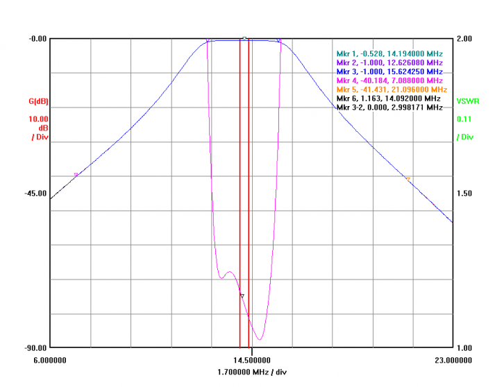
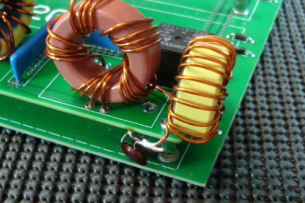
A close view of the 15m trap, tuned for maximum attenuation at 21.1 MHz reflecting the RTTY contest band orientation of the filter set. Some attenuation remains even away from this peak operating area. I think some additional attenuation could be achieved with a higher C, lower L value which would provide a higher operating Q. Something to consider on the next filter mod... 
A close view of the 40m trap, tuned for maximum attenuation at 7.050 MHz. The filter is more narrow banded than the 15m which is likely due to the higher overall Q achieved on 40m. Over 30 db improvement from the standard filter. 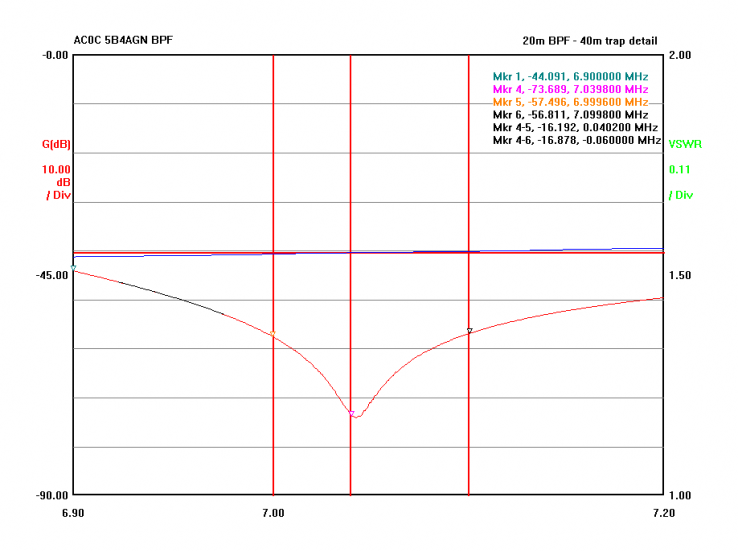
The modified filter (with traps added) in RED, vs. the standard filter in BLUE shown below. Note marker 4 and 5 indicating about 75db attenuation on 40m (a 35 db increase over the standard) and 59 db on 15m (about 18 db increase over the standard). Marker 1 shows only a 0.02 db insertion loss increase with the traps. And the SWR is improved (green line with traps, purple line-without traps). The SWR bandwidth is much more narrow with the traps, but it's still under 1.15:1 over the entire 20m band, and a near perfect 1.02:1 at 14.100. 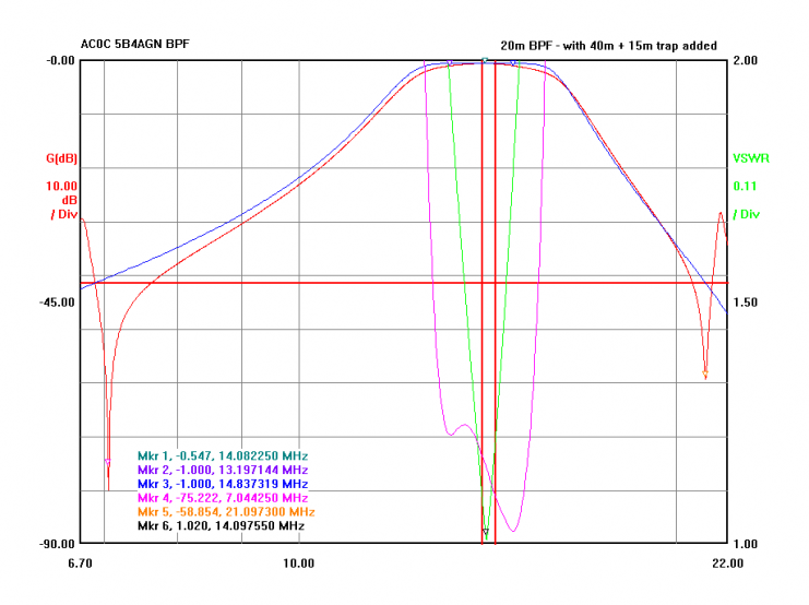
Finally, the completed modified 20m BPF module with the 15m and 40m traps fitted on the ends. Construction details of the two notch filters are: Trap | Cap | Inductor | 40m on 20m BPF | 220 pF 5% 500V silver mica | 17 turns #18 ga on T94-6 core | 15m on 20m BPF | 62 pF 5% 500V silver mica | 10 turns #18 ga on T94-6 core | 80m on 40m BPF (see example below) | 430 pF 5% 500V silver mica | 24 turns #18 ga on T94-2 core |
Peak attenuation points are trimmed by adjusting the turn spacing on the coils. Precision and patience is required. And once set, any physical adjustment in the traps will shift the operation frequency. So touching up the traps prior to closing the container is recommended. The settings, once achieved, are thermally stable - heating the cap and coil to moderate warm temps (with a heat gun) shifted the 40m down only by 5 Hz. And in normal operation, no heating should be expected. With respect to orientation, the trap serving the band with the strongest coupling (meaning highest signal level) should be put on the rig side - this allows the much larger BPF elements to provide the first stage of attenuation and that would minimize currents in the traps. Which means in my application, the 15m trap should be located on the rig side. The small yellow arrows point to the cap locations. The trap coil is at the end near the relay. 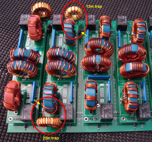
Example: 40m BPF with 80m Trap Added Looking at the 40m BPF (below), we can see roughly 45 db of attenuation on 80m and an excellent 65 db of attenuation to the 20m band. 65 db is likely adequate and so we will only fit an 80m notch to this board. 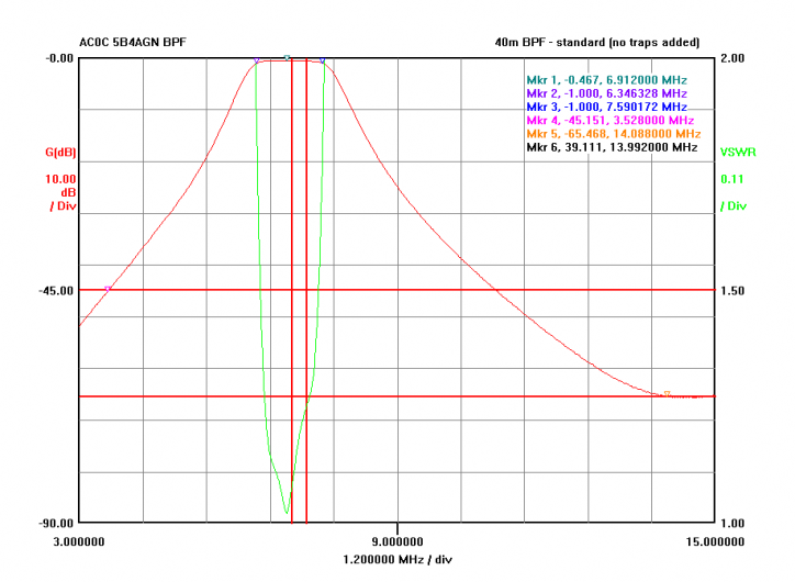
Here, the detail of the 80m trap is shown. The RTTY activity in most contests is above 3.550 and so 3.570 was selected as the target tune point. The red vertical markers are at 3.50 and 3.60 MHz. The notch improves filter attenuation by almost 30 db at the null - improving from about 45 db (standard) to about 70+ db at 3.570 MHz. And at least 15 db of additional attenuation is provided over a range of about 3.530-3.600 MHz. Trap construction details are given in the table (above, previous section). 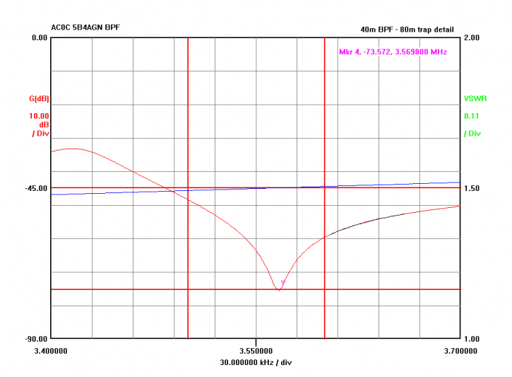
Taking a wider look, here is the 80m and 40m plot of the standard unmodified filter, for reference. 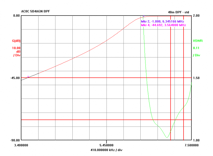
And here is the same bandwidth span, this time with the 80m notch added. Some minor touch-up of the in-band 40m SWR is added bringing the overall SWR down to 1.1:1 or less across the entire 40m band. 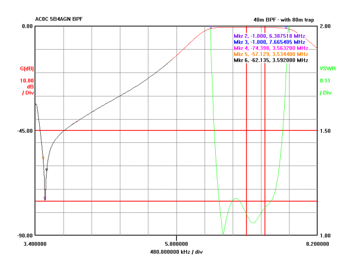
|