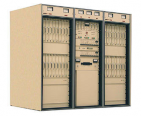
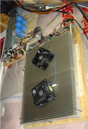
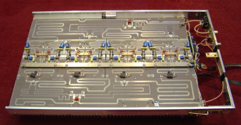
A cool KW for 6m thanks to the digital television revolution. Canada-based Larcan builds commercial television transmitters (shown right) and when the switch to digital came along, a lot of gear became obsolete, fortunately finding it's way into ham circles. These are great amps, designed for 24x7 operation and built for service in a commercial environment. There are a few variants of the Larcan module depending on frequency of operation (HiLo and LoLo) and power level (1KW or 1.5 KW). My module is a 1KW LoLo variant. The completed LoLo module (top, bottom and as-mounted) is shown in the following photos. 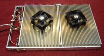
Implementing service using the Larcan for 6m is straightforward. Primary tasks are to provide sufficient power, T/R switching, cooling and mounting. What follows is an overview of this work here at the AC0C shack. Power Supply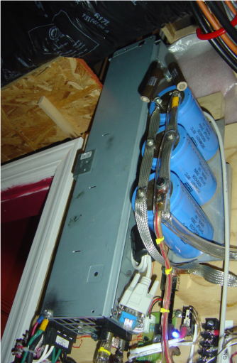 The amp power supply is from a Compaq computer server bank and is rated for 3KW (50V/60A) CCS. It's a large and heavy unit, with vent fans that make a wicked howling sound. The amp power supply is from a Compaq computer server bank and is rated for 3KW (50V/60A) CCS. It's a large and heavy unit, with vent fans that make a wicked howling sound.
The PS was mountied on a plywood backing with the fan-end positioned up high in the room. In their final resting point (wiring closet wall) the fans are up near the ceiling where a lot of natural damping materials exists, helping to calm the noise level of the PS. Thanks to this location, it's obvious that the amp is powered on, but the noise level from the power supply fans is not bothersome. The power supply assembly is shown in it's final mounted position at left. Preventative treatment to the power supply lines were in order. Switched power supplies (SPS) are notorious for generating tons of RF noise and with a 60A capability, I expected this SPS to be a troublemaker. A common mode choke was installed on the 240V AC line (the donut shaped core in the photo below) immediately before the PS input. Results are acceptable. With the bias set to disable with PTT, it's possible to see a wiggle in the noise floor caused by the SPS with the dummy load in place (a 0-5 dB 2-Hz oscillation that pumps the background heard in the rig). Fortunately the absolute level is pretty low because connecting the antenna to the amp (the normal use) easily masks the SPS hash. If the bias is enabled full time, the noise is undetectable. I suspect that the PS creates a bit more RFI when it's lightly loaded it makes more noise, and there is some coupling between the PS and the exposed T/R relay and associated wiring. In any event, that's a project for some later day. 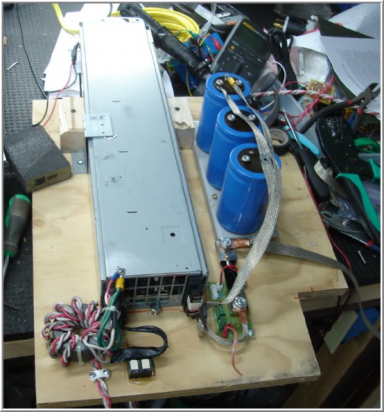
The Larcan is reported to be succeptable to oscillation and the recommended fix is to attach some big value cap next to the amp. I had a few huge caps on a mounting plate in my junk box, and with no other planned use in sight, they were pressed into duty here. I'm not convinced that there is actually an oscillation problem but the caps look good hanging there and at a minimum it adds some eye-candy to the assembly. Connections between the SPS and amp are made with 1/2" silver plated copper strap enclosed in clear plastic PVC tubing (slit to accommodate the strap). This provides a measure of insulation against incidental contact with the exposed 50V line; not dangerous but it would probably get your attention if you stuck your hands on the wires. A couple of relays needed for the various control aspects are mounted on the board as well. The SPS's PTT and enable lines are routed through the shack's Microham Station Master which enables the amp only when the rig is set to transmit on 6m. The entire power supply assembly screws into place on the closet wall, just to the left and above the mounting point for the Larcan amp, making R&R simple. Easy Instrumentation on the Cheap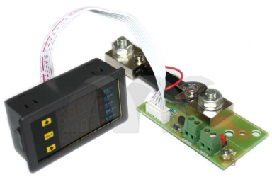
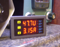
A convenient and low cost module sold by the eBay Internet vendor "nyplatform" proved perfect for the amp's basic instrumentation requirements. The module is composed of two parts, a sensor board (below) and the control head (right). The digital display provides voltage and current readings in two display lines. Additionally a touch switch on the display triggers a power enable relay mounted on the control board, serving as a convenient power switch/standby switch function for the amp. The unit has several user-adjustable alarm options built in, including an over-current sensor. Once triggered, the alarm will cut power to the SPS and will show the fault condition on the display. I setup the alarms to provide overvoltage at 54V and overcurrent at 42A. Considering the absolute maximum current for the FET is about 18A per (72A total), this is quite a conservative value and should keep me away from trouble. The undervoltage alarm was not used because there is about a 3 second lag between enabling the SPS and when the voltage move up to 50V - this lag causes the controller to falsly trigger the low voltage alarm. The Larcan has a small board that reads reflected power and so there is some protection against an antenna side malfunction - the board drops bias effectivly cutting the amp's output to a low level. The boards operation is explained in the Larcan technical documents. 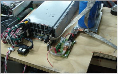
As shipped, the connection between the control display and the sensor board is a 6" 7-conductor ribbon cable. With the plans to mount the amp remotely (in the wire closet), a much longer run was needed. 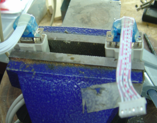
 The solution turned out to be simple; a pair of DB9 ribbon cable connectors were fitted to the existing ribbon cable (photo below) and a 15' serial extension cable was connected to the DB9. Type 43 ferrites were loaded on each end of the cable as a precaution both against errant RF pickup by the unit (should it be sensitive), as well as a buffer against any RF hash the unit may exhibit. In use neither condition has been noticed. The solution turned out to be simple; a pair of DB9 ribbon cable connectors were fitted to the existing ribbon cable (photo below) and a 15' serial extension cable was connected to the DB9. Type 43 ferrites were loaded on each end of the cable as a precaution both against errant RF pickup by the unit (should it be sensitive), as well as a buffer against any RF hash the unit may exhibit. In use neither condition has been noticed.
My plan is to combine this control head and a forward/reflected power indication of some kind into a small box which would set in the shack. For the moment, it just sits on the desk shelf. Modifications The modifications to the Larcan LoLo module fall into 3 types; optimization (efficiency), addition of the T/R and a few other misc items. Optimization 
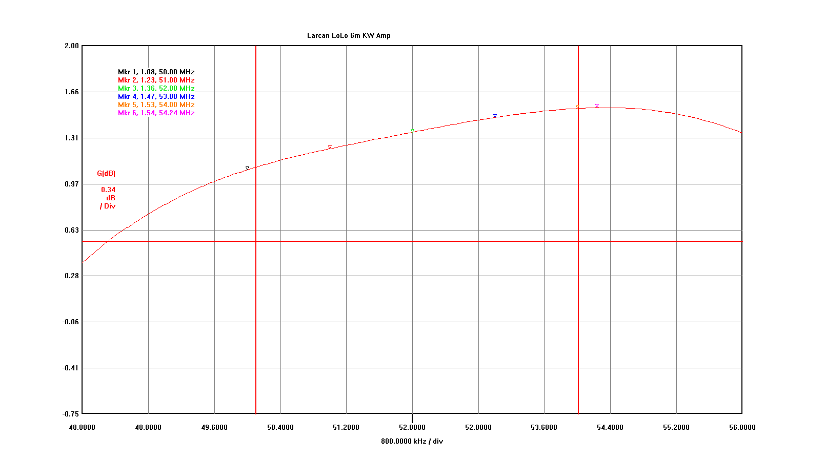
Based on the excellent work by Dave K1WHS, the tweaks to get a LoLo to sing along on 6m is pretty easy. The addition of about 20 RF-grade SMT caps shifts the sweet spot of the amp down enough to improve the efficiency, bringing the maximum output of the unmodified amp (about 600w out with 10w input) up to 1KW+ with 5w or so input. Download Dave's white-paper on LoLo modifications found HERE (4 Mb PDF). I started implementing Dave's modifications and could not get (at 50.1 MHz) the 22 dB gain that he observed, coming slightly shy of that mark by about 1 dB. A bit of additional experimentation was made - observing the gain plot with the VNA each time. The final transmission gain plot looks like this (below, add 20 dB to the indicated values to compensate for the attenuator used in the measurement). Click on the graphic for a higher-resolution view. 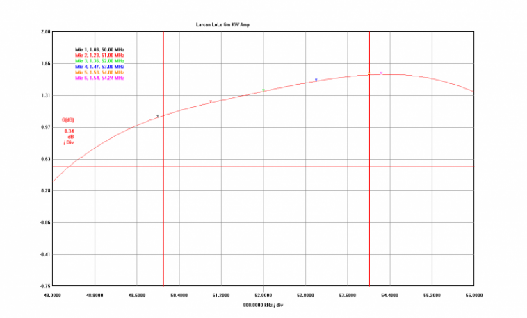
T/R Switching 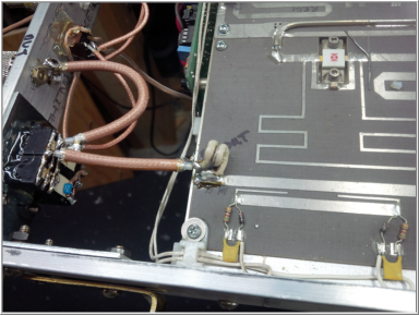
T/R switching was implemented using a pair of Tyco relays in parallel for the output, and using a low current RF type relay for the input. The input only needed to handle the 5-50W of drive the amp required (depending on input pad value) and so the requirements were non-specific. Even the impact of the ad-hoc wiring layout was not a problem because the input pad would guarantee a nice low SWR was seen by the exciter under all conditions. The output was of greater concern in that the 16A relays are specified at 60-Hz - not at 50 MHz. At 1KW, the output current is under 5A however relay contacts derate pretty fast with frequency. So a pair of relays in parallel combination produces 4 sets of SPDT 8A (@60 Hz) contacts on the back end. I had used the same relay in single units on 10m and below for years at the KW level without a single failure. Utility Modifications 
In this category are the supply lines for the 50V feed, control lines for PTT and the bias control. 
The 50V lines are hard-wired with 1/2" strap. A terminal block was added to provide the PTT line connection with a few unused terminals available for something in the future if needed. The PTT line is tied via a switch to the amp's bias line allowing the bias to be dropped when the PTT is not asserted providing faster cooling for the amp (see the switch mounted near the amp's center). In the normal case the amp's bias is applied all the time the power is on dissipating about 200w in the static case. Not knowing if switching the bias with the PTT line would be beneficial or not, I mounted the switch to have the option to change it on the fly. 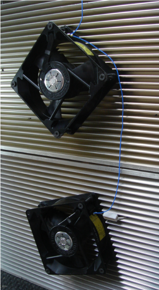
The prior owner supplied an aluminum frame to facilitate shipping and I have left that in place. With an added end piece, the frame makes for a useful "handle" to lift the beast with when moving it. Some metal bits were attached to allow the amp to sit on some screws placed against a plywood backing facilitating easy R&R. Cooling was a concern despite the massive heat sinks which cover the entire back of the amp. A pair of 24VDC fans were mounted on the heatsink and wired in series, fed by the 50V line. Those proved to be too noisy so a series dropping resistor was added to bring the speeds down such that the fans were inaudible. In KW-level power testing, I have not noticed the amp being even warm to the touch since the addition of the fans. The fans are held in place with long decking screws which have an interference fit pattern with the heatsink fins simplifying the mount. The input attenuator is shown below. The final attenuator value selected was 10 dB but for initial testing, a 6 dB unit was mounted. The typical place for the attenuator is to the left of the input power sensor but I wanted the sensor to reflect the actual input power in case that circuit were to be used for something later. This drove the attenuator's placement as it's shown in the photo below. 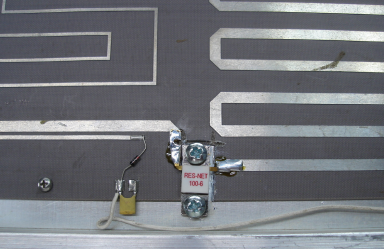
5-pole Elliptical LPF Filter To control any harmonic products from the amp's operation, a homebrew LPF has been added. The design is a 5-pole elliptical design, with the filter notch points aligned with the 2nd and 3rd harmonics (100.2 MHz, 150.3 MHz) of the common CW/SSB operation range. Design The design was created in Elsie. Schematic and Elsie plot of expected response is shown below. 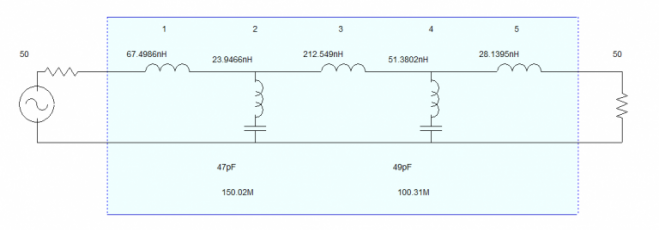
Build Construction started by measuring the caps with the VNA at 50 MHz. Elsie re-optimized the L values based on the actual cap values I had, and from that the physical coils were constructed, again using the VNA to measure their approximate value. Once the filter was completed, the coils were tweaked a bit to get the response as measured by the VNA to match the Elise plot more closely. The final result shows a pretty close match between the filter and the Elsie design. A photo of the filter showing the construction details follows. Doorknob surplus caps served as the physical mount for the coils. UHF connectors were used on the filter and amp over the more conventional N-series. And the use of UHF connectors will serve a ready excuse if I can't work a bit of 6m DX with the amp! 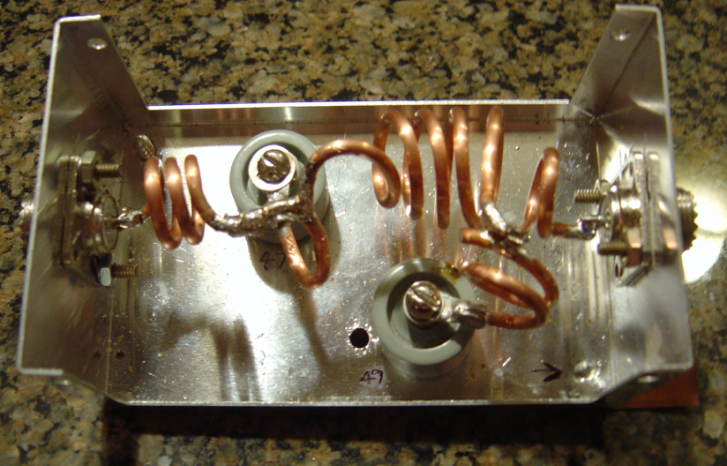
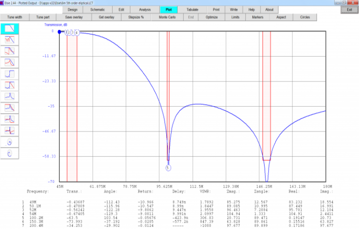
VNWA measurements of the finished unit show better than 60 db of attenuation at both target harmonic frequencies. Loss is slightly less than the Elsie model - a nice surprise! 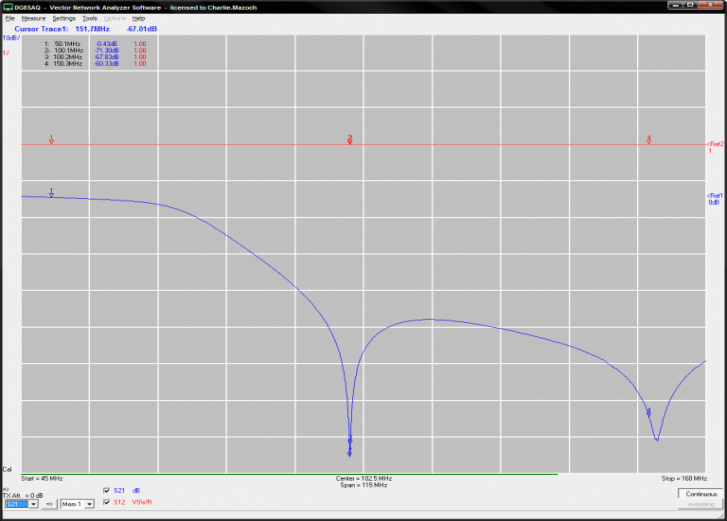
Before the 5-pole design was built, an earlier 3-pole design was built according to an Elsie design and the actual performance matched the design nicely as well. Given the relative ease with which the 3-pole went together, the 5-pole design seemed like it should work out as well. Power GainAt 50.1 MHz, the amp gain is about 21 dB; about 5 watts drive produces full 1KW output. Testing was conducted without the LPF in place. This is typical of what other hams have reported for the modified LoLo. I'm not sure what the max safe ICAS power level for the amp is. I know it will make 1300w without effort so it clearly has adequate headroom. 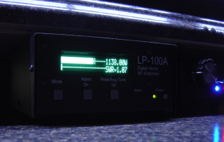
Drive | 3.8w | 4.5w | 5.1w | 6.3w | Po | 765w | 877w | 983w | 1100w | V | 50.7V | 50.7V | 50.6V | 50.6V | I | 33A | 35A | 37A | 40A | Pin | 1673w | 1775w | 1872w | 2024w | Eff | 46% | 47% | 53% | 54% | Pd | 912w | 903w | 894w | 930w |
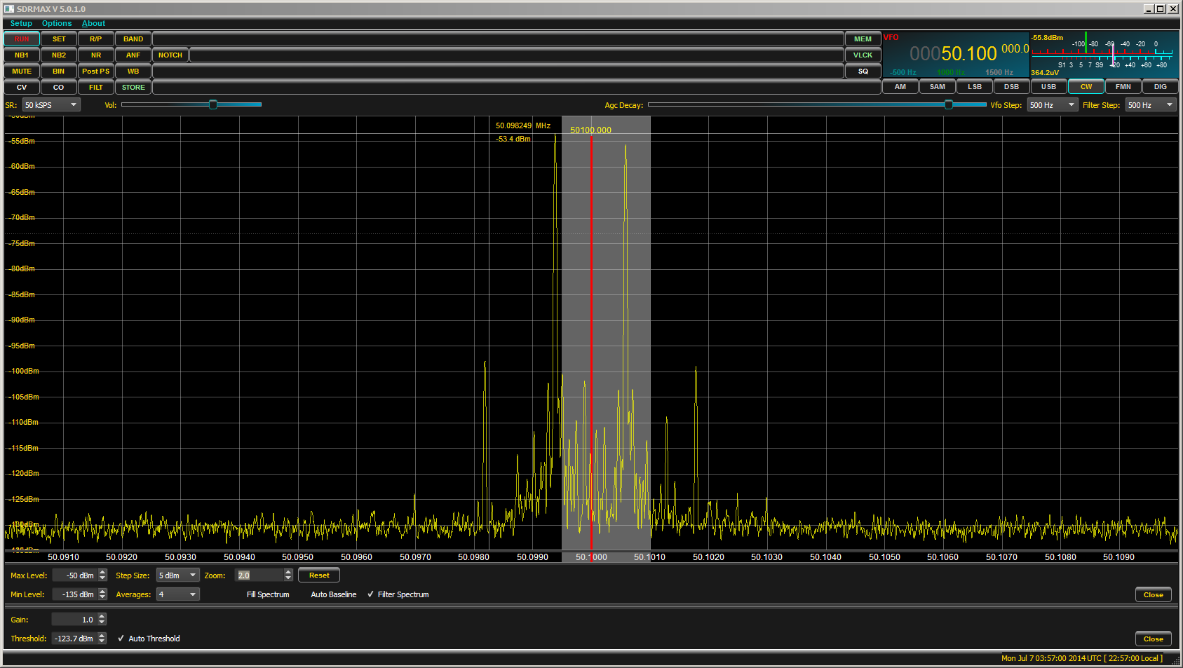
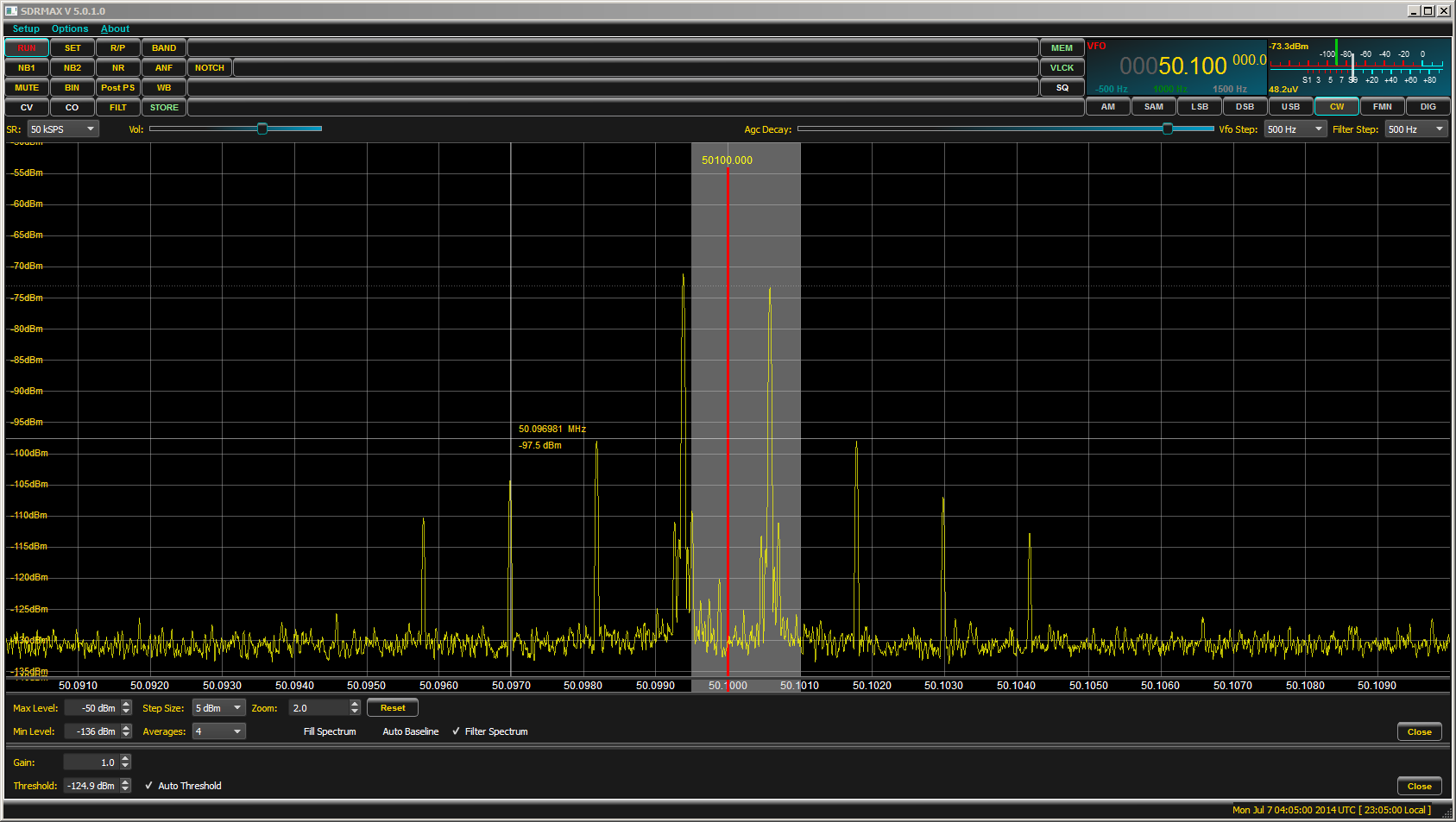
Discussion Given the high gain of the amp, it's clear that a mistake in rig adjustment may be a disaster. To prevent this, an input attenuator provides the amp a fail-safe protection capability, to a certain extent. I don't know what drive level would result in FET damage, but with the final 10 dB pad in line, that means even a 200W full-output of the FT5K would yield only 20W of drive into the amp. I expect this is enough drive to push the amp into clipping considering the power supplies 60A specification. Considering the 40A draw of the amp at 1100W, a current trip threshold may be a good way to implement further protection. This capability is built-in to the power control head (designated OCP - over current protection). Setting the OCP threshold at (for example) 45A would contain the amp to a safe range. This assumes the OCP trigger speed is fast enough to prohibit damage. The device was not tested for this but with an update period of 200 mS - and assuming this is the trigger speed as well - then we would hope that the amp could withstand an overload condition for 1/5 of a second. This is of course a very very long time from a FET perspective... IMD Performance Methodology IMD testing was performed by running a tone pair of 700 + 1900 Hz into the Yaesu FTDX-5000MP configured for class A. Levels were adjusted to give best IMD performance at the required drive level (25w from the rig, inclusive of the 6 dB attenuation pad, is about 6w into the Larcan resulting in about 1100w output). The test was run twice; once with the rig alone feeding into the dummy load, and then again with the amp at full power. Tests were conducted without the LPF in line. The purpose of running the test on the rig alone is to determine if it's a contributor to the levels seen in the amp; ideally the driving source (in this case the rig) should have an IMD level at least 10 dB better than the amp. The spectrum was measured by a QS1R lightly coupled to the coax line leading to the dummy load. Absolute values are unimportant, only relative measurements and the QS1R within this signal level range can be considered to contribute no error to the test result. IMD levels were determined to be the difference between the strongest of the primary signals and the strongest of the 2nd order IMD product. This is often called the ARRL method (the commercial method compares the lowest primary signal to the highest IMD product's level - roughly a 6 dB lower value). Measurements The rig's primary tone shown here. Click on any of the plots to view a high-resolution version. 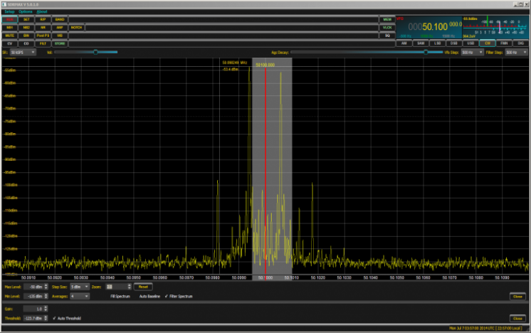
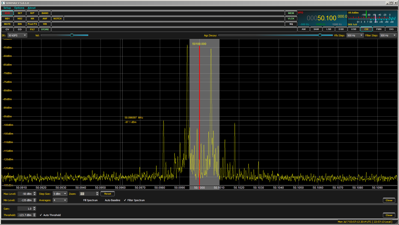
The rig's IMD product is measured here. 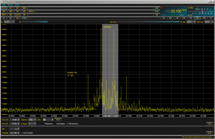
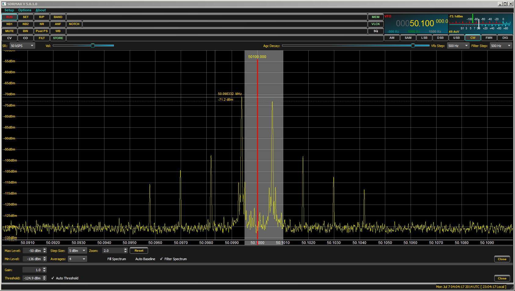
The following two graphs are of the amp's output signal. Here shown are the primary tone's measurement. 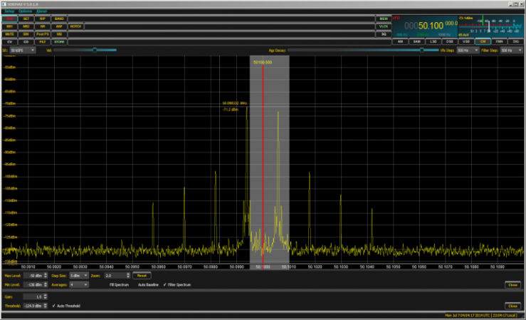
And here, the amp's IMD product level is measured. 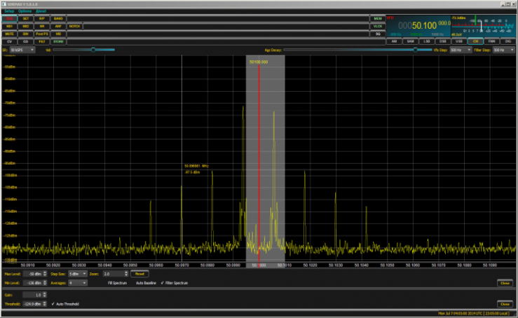
Analysis and Results Assembling the 4 data points into the following table and comparing the difference, we find the following results. | Primary Tone Level | 3rd Order
Product Level |
Difference | PEP
IMD Level | Rig | -53 dBm | -97 dBm | -44 dB | 50 dB | Amp | -71 dBm | -97 dBm | -26 dB | 32 dB |
The FCC requires 30 dBc levels and (using the ARRL method) the amp meets that requirement. Adjustments in idle bias or other circuit mods may improve this value. But given that 6m is so infrequently open, I think we are going to bring the benchwork to a close and kick off the "run-it" phase ! To-Do List - Switch out the 6 dB input pad for a 10 dB unit allowing the transmitter to run at 50w
- Mount control head in an enclosure.
- Add forward/reflected power indication to control head box.
- Add SWR and overdrive cutout protection
- Increase isolation of SPS and amp - shield T/R relay area?
- Power output vs. bias adjustment vs. IMD improvement?
CreditsThanks to the guys who have gone before, especially Dave W1WHS who did the early amp analysis. To Dick K5AND, Bill W7AAZ and Jim W7OUU for help of several flavors - parts, advice and suggestions. Links http://www.users.on.net/~pedroj/larcans/ https://groups.google.com/forum/#!forum/larcan-6m-amplifiers http://members.rennlist.org/warren/larcanamps.html http://www.mmra.org/larcan/ http://www.larcan.com/Broadcast_Solutions/viewprod.aspx?prodcatid=31392&productid=30252 http://kh6hak.tripod.com/fet-kilowatt-amp.html http://www.worldwidedx.com/amplifiers/134179-6m-larcan-conversion.html 73/jeff/ac0c |